What settings are required when using the PROFIBUS board AB3601 (manufactured by HMS) on the YRC1000?
By using this board, you can exchange YRC1000 general IO data with other PROFIBUS communication stations.
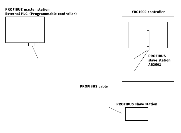
System configuration
When using the AB3601 board, the AB3601 board can only be used as a slave station:
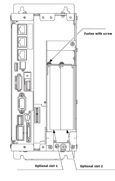
Board mounting position: PCI slot inside the YRC1000 control cabinet
Maximum number of input and output points: input 164Byte, output 164Byte
Communication speed: 9.6Kbps ~ 12Mbps
Board allocation method
To use AB3601 on the YRC1000, you need to set the optional board and I/O module according to the following steps.
1. Turn on the power again while pressing the “Main Menu”. – Maintenance mode starts.
2. Change the security mode to management mode or security mode.
3. Select “System” from the main menu. – The submenu is displayed.
4. Select “Settings”. – The setting screen is displayed.
5. Select “Optional Board”. – The optional board screen is displayed.
6. Select AB3601. – The AB3601 setting screen is displayed.
① AB3601: Please set it to “Use”.
② IO capacity: Please set the transmission IO capacity from 1 to 164, and this article sets it to 16.
③ Node address: Set it from 0 to 125, and this article sets it to 0.
④ Baud rate: Automatically judge, no need to set it separately.
7. Press “Enter”. – The confirmation dialog box is displayed.
8. Select “Yes”. – The I/O module screen is displayed.
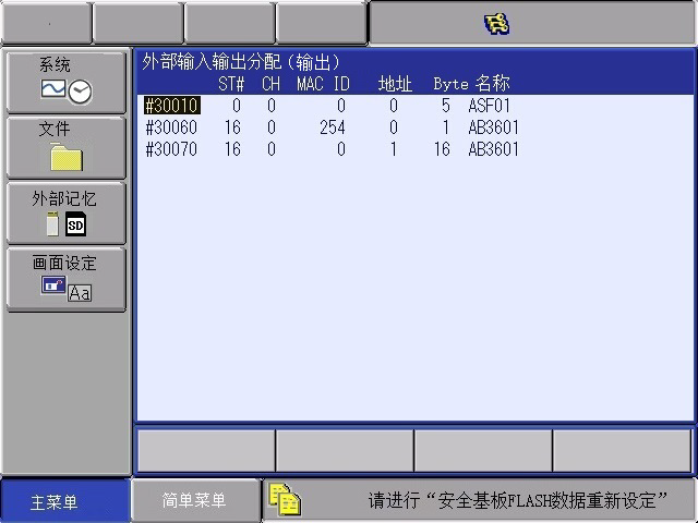
9. Press “Enter” and “Yes” continuously to continue to display the I/O module screen, display the IO allocation results of AB3601, until the external input and output setting screen is displayed.
The allocation mode is generally selected as automatic. If there is a special need, it can be changed to manual, and the corresponding IO starting position points can be manually allocated. This position will not be repeated.
10. Continue to press “Enter” to display the automatic allocation relationship of input and output respectively.
11. Then press “Yes” to confirm and return to the initial setting screen.
12. Change the system mode to safe mode. If the safe mode has been changed in step 2, it can be used directly.
13. Select “File”-”Initialize” on the left border of the main menu-the initialization screen is displayed.
14. Select the safety substrate FLASH data reset-the confirmation dialog box is displayed.
15. Select “Yes”-after the “beep” sound, the setting operation on the robot side is completed. After shutting down, you can restart in normal mode.
Post time: Mar-05-2025


